S4 B5 2.7tt powered Cayman
- highpressureperfor
- Dec 4, 2023
- 20 min read
Updated: Jan 5
After searching for kits for Cayman swaps I decided to make my own using a 2.7tt engine from a 2003 Audi Allroad. This swap will replace the very unreliable 3.4 liter Porsche engine in my Cayman soon to be given to my son.
Carnage from spun rod bearing, seems pretty coming in these other than bore score. So I had all the issues, bore scoring was bad, rod bearing was gone which took the crank and crank carrier along with the driver side cylinder half.


The doner car will be Speed yellow but now is still wrapped in green.
2008 Cayman S

The important things first I had to upgrade the stereo to my teenagers liking. We installed a Kenwood stereo powered with the OEM Bose amps and speakers.

Next on the list is getting the donor motor, I found one local for $650, looks to be ok but not bad for a mock up engine and or just test fit for the kit.
Yes, I got out in the rain it was a miserable day to be at a junk yard for sure.

I was pretty happy since the motor actually spun over by hand and was not locked up, the plugs look good and the little K03's look ok too, testing the Porsche 6speed transmission to the new engine. So far so good.

I am planning on having an install kit made with instructions, I just need to work out all the details first. The plan to get this running is March 2024, then I will work on how to market the kits.
Stay tuned......
Got the car ready for paint. Sending to painter to get it back speed yellow. The fenders, lights and bumper are 987.2 spec so it should look a little better. Also installing a rear wing side skirts and a front splitter. Hopefully it will turn out good.


4-15-24
Car is one color now. Time to put her back together and get with the engine swap!


Time to start putting the Cayman back together. The painter is done and will pick after the windshield guy installs the new windshield.


My advice is do not buy a car that someone has worked on. The previous owner did some tinkering with the car but it seems everything that was touched has either missing bolts, not tight or broken. The process of fixing the previous neglected items are slowing my progress and motivation down.


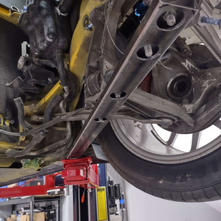
After the first attempt to test fit the engine which was not as successful as anticipated.


Good news, did some more test fitting and figured out what was needed. I had to remove two tabs on the engine cover area.

This removal enabled the engine to move up enough to get the transmission mounted properly with out having to move the OEM forward location.


The transmission is about 1.5" lower which is a bummer but the sway bar still clears. Will report once in place. I made a prototype drawing to replace the OEM transmission mounts and engine cradle.


The plan was to keep the stock twin turbos on the S4 b5 engine. After removing them as it was a PITA, I decided a single might be better. Once the cradle is made I will see where to put the single and make sure it is possible.
I found a small clearance issue with the passenger side valve cover. It was very close to the Porsche coolant tank. It did clear but I was worried that if the motor moved any it could damage the coolant tank. So I removed the valve cover and removed the bung that was close.


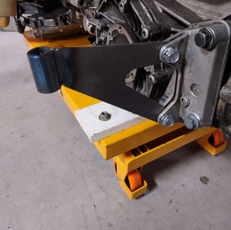
Made a test trans mount. It worked out better than expected from my hodge podge card board cut out.


Looking at the intake manifold I believe I will have more space for the throttle body if it points to the rear of the car. So I reversed it to test out.


After thinking about the engine mounting method of Porsche I might redo the cradle I have designed up. My fear is that the rear transmission mounts really do not hold the engine/transmission from moving forward or backward, they just basically hold the weight. Maybe over thinking it but will need to do some homework on this. I will be using the OEM Audi motor mounts on the sides of the engine which will hold the engine but need to confirm that the engine will not move forward. Maybe I can use the OEM Porsche front mount and tie it in to the front lower OEM Audi engine mount. This will still be isolated as the OEM Porsche was. Just thinking about it now.
12/1/2024
Baby steps. I made the base of the motor mount cradle. Two sides that replace the OEM aluminum braces and also made a bracket to replace the front motor mount.
Now I need to finish up the transmission mounts and get the motor back in position to get the rest of it.


12/4
Still making some parts for all the mounts. Going smoothly so far.
Made some transmission brackets and mounter mount brackets. Amazingly enough what I had in my head is actually fitting and working out great.


This project is moving a little slower than expected but I am making headway. The engine cradle has been finished and is back from the powder coater. I am pretty happy with it although if I did it again I might change a couple of things about it but all in all it will work for this car.
I started the engine prep and that is turning out to be fun. Waiting on parts and trying to figure out some of the wiring. so far so good.
Here are some pictures of the progress.


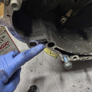
Above is some stainless oil feed block offs I made. I might use the oil pressure sensor location for the turbo feed line. Egr block off plates, doing some needed maintenance, new water pump, new thermostat and housing, looking at cross over pipe to modify it and take off some of the brackets not needed. Waiting on cam seals and front and rear main seal.
Coolant plugs added, timing belt, cam seals, water pump, idler pulleys, valve cover gaskets and tensioner is installed. Modified the coolant pipe, blocked off the turbo water lines. The turbo I am using is only oil cooled. Installed a plug where the green coolant switch was and removed all the little brackets.


I planned to modify the exhaust manifold to add a v band to make my single turbo set up but decided not to use the OEM manifolds. The OEM manifolds look to be very restricted so I will have to figure something out there before making the single turbo kit.

All three exhaust ports are into a 1" tube. I guess it works but I could not bring myself to use this.
I did test fit the injectors. I purchased Bosch 630cc injectors. They fit great. Planning to add AN bungs to the fuel rail to make it easy for me to make fuel lines and also need to buy or make a banjo to -6an for the power steering pressure line to the pump.


Working on the transmission mounting bolts. I had to tap three of the bottom bolts on the Porsche trans to accept the bolts on the Audi lower oil pan. No big deal the holes are already there to help locate. Also one of the top mounting through holes needed to be a touch bigger for the bolt clearance. The hard part is the lower starter bolt. I either need to plug the bigger hole next to it and drill or tap it for the bolt. Once I figure it out I will update the blog.


Ah ha, I figured out the starter bolt. It is a M12 x1.5 bolt and a Y drill bit for the tap drill. I took a chance and drilled the small hole all the way through and it worked perfectly. I measured the bolt protrusion into the Audi block and if I can get all the bolts 15mm I am good. Also the started bolt needs to be tapped deep enough to have less than 49-50mm to clamp the starter down. I am using all the Audi bolts so they are pretty long.


The next thing on the list is making a jig to drill the crank sensor hole in the transmission. It appears that the Porsche transmission has a boss cast in and ready for a through hole and tapped hole for the sensor. I like it! Thanks Porsche/Audi.


3/27/25
Waiting on parts. I ordered the incorrect flywheel and pressure plate. Anyway once those get here I will start getting this moving.
I did get the turbo oil feed line started. This is not necessary but will work. I replaced the OEM Audi oil pressure switch with the OEM Cayman switch so the dash will see low oil pressure. I bought an adapter to screw it in to the Audi oil pan and then put a m10 to -4 an in the other side for the oil feed to the turbo. I guess I could have used the OEM Audi turbo feed line and one block off. Either way will work. I had to grind off a little on the AN fitting so it would not bottom out.


The engine is pretty much ready for install once I receive the flywheel and mount the transmission. I am excited to get this in the car finally.


I found another snafu in my idea. I planned on using the OEM manifolds and just add v bands to the end for the turbo kit. To my surprise the manifold runners are 1" ID. What the heck is that?! I was disappointed and discouraged in having to fabricate manifolds until I ran across these super cheap China ones on eBay. I would never buy these but I decided it was worth a shot. I can not even buy the materials to fab these for what they cost.


I will cut these and put these v bands to get started.
I finally received the flywheel and flywheel bolts. Now I will drill the hole for the CAS in the transmission. I need to make a drill fixture first. I cut the manifolds and had to grind down one of the screw bosses on the head to get them to fit properly. It was just about 1mm of interference. No big deal.
4/4/2025
I did modify the fuel rails and welded -6an ss bungs on them. There are probably fittings that work but I had some and a welder. So I just did it that way. Also welded a bung for the power steering pressure line.


Got my 18mm drill bit and made a fixture to drill out the transmission for the CAS. I need to test it and see if it is close enough. Now I think it is a little too far away at 4mm but will mount the transmission and get a better measurement.


Well, it's going slow for me. I revisited the CAS and mounted the transmission to the engine. I wanted to measure the clearance in position. I filed the trans to achieve the correct or what I think is correct which I set it at 1.2mm. I also used a step drill to make a counter sink for the oring on the CAS. Not really happy with that since I spent so much time drilling the 18mm hole.
The conundrum I ran into was that the long starter bolt was 110 mm long but I need a 120mm, I found one from belmetric so I was happy with that. So I was excited and stuck the motor back up in the car to figure out everything else.


Engine ground cable done!


Coolant system.
Use OEM water lines to oil cooler and out
Modify the front cross tube as shown


Use gates 23184 coolant hose , it is an upper hose for an LS engine. The OEM Cayman hoses measured 1 3/8", hopefully the 1 1/4" coupler will be enough. Or i will make the correct one later.
Update: I changed the coolant coupler to 1 1/4-1 1/2" and it fits perfectly.
Cut almost in half and both sides can be made. Also cut the OEM Cayman hoses, use 1 1/4" couplers. The 90 degree hose fitting is a ECS part number 3072294 but it show heater hose connector on the web site . But it fit and worked for the radiator outlet.


Now for the front cross pipe , I ordered a OEM Audi hose . Cross pipe to water pump. Also a Y junction. The Y. Will go to the Porsche reservoir. So I removed the 19mm block off cap I had previously had on there.


Heater hoses,
I had to use 4 hoses to make 2. I have the part numbers on my build list once completed, I will ad some heat shielding to the back side just to keep the hoses from getting too hot since they are running over the exhaust. I will also investigate a different route method but this one seemed to work out ok. I will also . One modification to the rear cross pipe needs to be made. The 90 degree push on fittings are clocked by the tabs on the pipe. The orientation of the 90 needs to be pointed to the passenger side. I just had to grind off one tab to make the fittings work.


Heater hoses assembled: looks like it will work out pretty good. I am also thinking to move the bleed port back up front so I connect it to the reservoir.
Either way will work I just need to test which way is easier.


Power to starter , alternator.
Use the OEM cayman connector and cut one of the wires off and put heat shrink back on it. I plan to mount this on top of the engine close to the OEM Porsche
I found a resistor on the Porsche alternator so I removed it and will put on the Audi alt.


Return fuel line:
I used -6an hose and run in the same clips as the OEM fuel pressure line. Just cut away the clip and it will work .


I have to come back to this later. I had to order a special tool for the tank retaining ring. I tried to remove it but would rather not damage it.
Working out the details of the return. So far not bad. The return line from the engine will just be a -6an line which is connected to a GM style clip on fitting. This is not necessary but I was trying to keep the Porsche fuel connections similar where the connectors are in the OEM locations and pulling a motor would be the same process. Here are some pictures of the return and feed line connections.


Now to the fun part.
Remove the fuel tank retaining ring and remove the tank fuel level and pump assembly. I used a bulk head for the return and had to do some grinding to the plastic cap to get the return bulk head in place. I need to make sure this works if I plan to do another one. This is just my idea on how to do the return. I am sure there are other ways.


After installing this I will need the return to exit at a 90 degree angle to be able to connect the return line in the small space above the tank. So I will order the correct fittings and try again.
More on fuel system. Wow this sucked.
I planned to use a 450 walbro pump which does not fit in the OEM surge tank. I ended up breaking the surge tank so I made a replacement one. Still in the works but it is coming together.
The fuel level pick up has to be modified and zip tied to the top hat. No big deal and it is sturdy enough to work. I wasn't excited about a zip tie holding it but it actually worked out better than expected.


I will be adding a fill valve on the side of the surge with a Venturi pump on the return to pull fuel into the surge tank from the driver side of the tank. So far so good. Here are some more pics of the surge tank. I am almost done. I am ordering some corrugated hose for the return and pressure lines. So I am happy with the process so far. I did some extensive and very technical testing in my kitchen sink for the fill valve. It is pretty cool how well it works.


The hoses arrived for the fuel system. I assembled everything to install until my awesome fill valve stuck out too much and now the catch can won't fit in the tank. I am super bummed right now.


Fuel round two:
Ok, I modified the surge take so it will fit in the tank. I did test fit it this time before welding it up. When installing the ring to hold the fuel top hat down I had to grind out the center so it would clear the return line. Probably a better way but this is how I did it. I started grinding sections but ended up just going 360 degrees around to make it easier. Just take off the inner lip and the return line clears perfectly.


Power steering:
I bought a factory hose for the power steering suction hose and this might work. Also added the return hose and plumbed everything in for test fitting. I would like to put it in front of the engine but it would be hard to fill from inside the car. I will move it if this does not work out.


Well, I needed to move the power steering reservoir, the easy place to put it like above was perfect until I needed to make an intake pipe to the air filter. The air filter will be tight so I moved the reservoir closer to the front and mounted it on the valve cover. I also needed to cut the return line which actually worked out well. I do like this better since everything is mounted in the engine. Will be easier when removing the engine.


Wiring:
The wiring has begun! So far it it not that bad. I am making a spreadsheet so it will be a little less confusing. Unfortunately my harness was cut in some places so I have to do a little more investigating on where the cut wires went to. It is a good idea to make sure the harness is in perfect condition before tackling this. Being my first Audi it makes it a little more difficult to say the least.
I have to research the back up light diagram to get them done, the AC fan wired into the harness, the AC clutch wires in and the rest of it.

The black box on the left is the can bus conversion box from renn2.7, he sends a wiring diagram to re pin the Cayman ECU plugs which go to the s4 b5 harness to make everything work. The only thing I found not on the list are above. AC, back up light switch, and AC fan. Once I find out how to get those in I will update the spreadsheet.
The s4 b5 ECU will be mounted in the Cayman OEM ECU location with the can bus box next to it. Everything should fit nicely and under the interior to all be hidden.
Update on the wiring, I am 99.9% done. Basically I have the MAF and MAP left and once I figure out were they will be placed i will be able to pin those connectors and plug in.
I need to figure out a seal for the harness through the firewall. No big deal but will address it.
Wiring has been confirmed. I went through the spreadsheet of wires and confirmed continuity on all the wires to each pin on the DME. Also confirmed wire color to S4B5 DME Pinout and position.
The Audi DME fit snugly between the Cayman mounting stud so the Cayman OEM mounting nuts held the Audi DME firmly to the body. I removed a section of the foam on the rear carpet and it all fit and is hidden just like factory.


Here is a screenshot of the wiring needed. Once everything works i will publish it.

Tuning:
I have 630cc injectors
OEM MAF
OEM MAP
Single borgwarner 51-67 turbo
External Wastegate target 15 psi
The ECU has been mapped by Tunezilla. It was about a week turn around.
Remember to ask for the immobilizer delete as I did not and had to send it back.
Turbo kit: TBD
Issues to over come.
Was planning on using the stock Cayman air box. I forgot to install it before the engine was put in. So now it is impossible to get the box into position.
The angle of the throttle body is very undesirable and leads to a very challenging intake to IC routing. There is not much room but I will figure something out. Done
I am going to use a Air to Air IC. I know ATW might be better suited but I am determined to use ATA.
Fitting a cat and a muffler , done.
Getting a good path for the turbo intake from the air filter.
Returning the oil to oil pan from turbo. Done not bad.
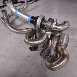
The turbo kit has begun:
The hot side of the turbo kit almost completed. I used 2" tubing for the down pipes and cross over and merged the cross over to start the 2.5" piping to Turbo exhaust housing. The turbo is mounted to the back of the transmission using a mavin small cartridge mount. The muffler and cat I planned to use might not work but I will try to fit something in the driver side muffler area as the passenger side will be for the IC. I am running out of room quickly. I will be using a exa pump to pump the oil back to the engine which I mounted as low as possible to the rear trans mount bracket. I also made a extra plate to brace the trans mount. I accomplished #6 hurdle maybe.


Next is running oil return and oil feed lines to turbo:
Using a 034 motorsports -10 an adaptor, and all -10 AN fittings and line to the turbo through oil savage pump. Seems to be straight forward but we will see if it will work. I also used a 36" -4AN line for the turbo oil feed. The only issue I see is that the 90 degree oil feed line needs about a 1/4" clearance which now it does not have. The line is touching the heat shielding on the bottom of the car. I should have lowered the turbo a bit to compensate for that.


Exhaust:
I started the exhaust fabrication, I wanted to have a muffler and a catalytic converter so the space was limited. Just need to finish running the Wastegate back into the exhaust and finish up the exit.


Really not part of the turbo kit but the intake needed to be modified for my placement and purpose.
Please don't judge me too much as I am making all this up as I go. No plans just overcoming issues as I figure things out.
I plugged off all the vacuum ports from the Audi intake Manny.


The two ports in the rear are not going to be accessible seeing that I flipped the intake 180 degrees to point the TB to the rear. Also the front port was removed so I could flip the TB 180 and mount it upside down for vertical clearance. I just shoved some aluminum plug in the holes and welded them up. I am sure there are better ways but this is how I did it.
The port on the top of the manifold will be used for the brake booster. I plan to drill and tap it out to accept a -8AN to 3/8" NPT fitting. That's the plan anyway. The only port I left was the OEM port to the FPR.
I had a difficult time welding the bung the top of the manifold for the npt to barb fitting. Not excited about it but hopefully this will work and have enough clearance.


Working on trying to make the cold side of the IC pipe. The throttle body is at a terrible angle and makes it difficult to get down where needed. Anyway, I am 3d printing some test parts to make it happen.


For the vacuum port I used -8an hose rated for vacuum. I was planning on using the OEM plastic hose to insert into the quick disconnect under the car. The -8 ID was a little small to fit over the plastic hose and I was not confident that after installing a hose clamp it would not crush the plastic. So I made an aluminum adapter to do the job.


The intake is on, hopefully for the last time. Injectors are installed. They are a little tight with the ev14 adaptors so if I do it again I will just put the correct connectors on the harness. Now to check for fuel leaks. I am just scared to turn the key on.
Wiring cont.
No smoke came out when key was turned to on position. That is good news. All brake lights, reverse lights do work. I primed the fuel pump manually to check for leaks. No leaks. Tested the starter signal but ( with wire disconnected from starter) the dash board message was press clutch pedal. Now I am assuming it is because there is no oil. I am getting a oil level malfunction on the dash. So I will fill it with oil and try again once I get the turbo drain line complete.
I test mounted the catch can. I will modify it to have three ports and plumb the hoses to the catch can. I had an old all-star aluminum catch can from my race car so I repurposed the catch can to use for the project. I am running out of space quickly, this seems to be a common issue! , it's the little things that will get you. But this location seems to be ok. I have never mounted a catch can so low so I will have to see it is will be sufficient and work properly. I do have an issue with snaking the pcv hoses back to the catch can using the correct hose material. I might be forced to use silicone hose which is not suitable for oil and fuel. The silicone hose routes nicely as I need it to bend around some thing to get to the catch can.


I moved the coolant bleed port to the front position and added some heat shielding to the harness around the starter. The bleed port will connect to the coolant reservoir.


Air intake from turbo to air filter.
Started fabrication of the intake. I am concerned with the amount of space to fit a proper size air filter but I need to get the intake routed first and tackle that once the intake is routed. It's tight but there is just enough space. Just enough!


I am getting down to the nitty gritty on this, the intake has been a challenge and the first idea failed along with the second. I moved my power steering reservoir so I can have a clearer path for the intake to the filter. I mistaking used a OEM MAF sensor which has weird sizes on the in and out. I would do a aluminum after market one if I could and did not already have a tune complete for the OEM MAF.
Once I figure this out the next issue is routing the BOV. It looked easy but once again it is not for me.
Finish up the intake and BOV, and the exhaust tip. The BOV just goes over the transmission from cold side to air intake. I need to do some small heat shields for the headers to keep the inlet air a little cooler. Will get to that later.


The engine I got from the junk yard did not have the pcv system on it. I did not want to buy a OEM one since I was unsure if it would fit or not seeing my space is limited and I flipped the TB 180 degrees. Anyway I made a simple pipe to connect everything and run to a catch can I had laying around.
Once it is running and driving I will be able to see if it will work ok.


Now for the interior, putting everything back together.


The engine cover will need some slight modifications to have enough clearance for the throttle body. It is about 1/2" interference and I also cut off the mounting points on the rear so those will need to be taken care of.
But the car is ready to test and see if it starts! Finally its time.
Success! It runs! After the test drive I discovered some small issues. Somewhat Porsche issues and Audi issues.
Cams seals are leaking (fixed)
Key fob does not work. But I don't know if that was a previous issue. I believe it is because the alarm horn was disconnected.
The gas gauge is at zero, it moved a little after putting 2 gallons in it. I drive it to the gas station and added 8 gallons. The gauge then went to below zero. (Fixed)
I have a P0340 code , cam position bank one. Will investigate that.
I have a couple of codes I will get deleted from the tune as I am not using some of the sensors that the codes are for, that should be no big deal. (Fixed)
The clutch is engaging near the bottom of the stroke. I assume it is the engine spacer that now I realize I might not even need it. (Fixed)
Getting a message for oil level sensor. Need to investigate that too.
The good news is the car ran fine. The cruise control works, speedo works, coolant temp gauge works, the PASM light reset after drive. I need to finish up some small things to get it ready to do some boost testing. But so far so good in my book.
Quick update 1/5/26
-I fixed the gas level sensor so the gauge works now. That was my bad in install.
Replaced the cam seals with OEM seals and that leak has been solved.
Fixed clutch issue. Pics below and detailed below
Still have oil level issue but have not got to that yet.
Investigating cam position code now.
Fixed the weird codes with O2 sensors and n75 valve. So only code left is 0340.
The engine runs great even with the cam position sensor code. But I need to get that fixed .

Clutch fix:
Since I used the spacer between the engine and the transmission which is 11mm thick I found a clutch masters throw out bearing that was 10.2mm thicker than the factory Porsche one. After looking at the TOB I might just make a spacer to install on the OEM TOB to get the 11mm but this one works well.


The very sad thing to this entire project is that if I try to show someone all the work I did I am unable to do so. Everything is hidden and the car looks and sounds the same as a 987 but with turbo noises.


